TPL Communications PA6-1AC amplifier: Difference between revisions
Brian Wilson (talk | contribs) mNo edit summary |
Brian Wilson (talk | contribs) mNo edit summary |
||
| (2 intermediate revisions by the same user not shown) | |||
| Line 14: | Line 14: | ||
I got it in a case that matches my Magnavox GPS, with the label Series 9000-WP on it. I took it out of the case to improve airflow, reduce the number of connectors in the RF signal path, and to make the overall package smaller. | I got it in a case that matches my Magnavox GPS, with the label Series 9000-WP on it. I took it out of the case to improve airflow, reduce the number of connectors in the RF signal path, and to make the overall package smaller. | ||
I am powering it with a [http:// | I am powering it with a [http://web2.murraystate.edu/andy.batts/ps/powersupply.htm converted Mini-ATX power supply] (Shark Technology SFX180-A2). | ||
I left one set of Molex drive connectors in place but cut off all the other wires inside the supply. The Molex connectors could be used to supply +12 and +5 to something later on. | |||
I added a SPDT toggle switch between the green PSON and GND to switch the supply on and off. | |||
For an ATX supply to stay on, there has to be a load sensed on the +5 supply. One approach to this is to install a 10 ohm, 10W resistor between +5 and Gnd. I left two wires available for this but will be using +5V to power a microcontroller so I left it out. | |||
One yellow +12 and one black GND are wired to a 15A Powerpole pair to power the radio modem, the remaining yellow and black wires are bundled and connected to another 30A Powerpole pair to power the amplifier. | |||
This power supply has two wires attached to pin 11 on the motherboard power connector, orange +3.3 VDC 20awg and orange 22awg sense wire. These two wires should be joined. | |||
New supplies have a sense wire that needs to be hooked up instead of -5V. This one has a -5V supply so I don't need to concern myself with that. | |||
Latest revision as of 17:00, 28 February 2010
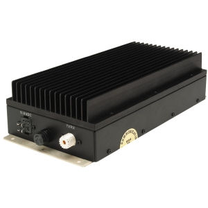
I am using this amplifier with Pacific Crest Radio Modems

TPL Communications
Model PA6-1AC-SSR
S/N 8144
DC In 13.8V (11-15)
DC Current 8 AMPS
More complete specs are available directly from TPL Communications.
I got it in a case that matches my Magnavox GPS, with the label Series 9000-WP on it. I took it out of the case to improve airflow, reduce the number of connectors in the RF signal path, and to make the overall package smaller.
I am powering it with a converted Mini-ATX power supply (Shark Technology SFX180-A2).
I left one set of Molex drive connectors in place but cut off all the other wires inside the supply. The Molex connectors could be used to supply +12 and +5 to something later on.
I added a SPDT toggle switch between the green PSON and GND to switch the supply on and off.
For an ATX supply to stay on, there has to be a load sensed on the +5 supply. One approach to this is to install a 10 ohm, 10W resistor between +5 and Gnd. I left two wires available for this but will be using +5V to power a microcontroller so I left it out.
One yellow +12 and one black GND are wired to a 15A Powerpole pair to power the radio modem, the remaining yellow and black wires are bundled and connected to another 30A Powerpole pair to power the amplifier.
This power supply has two wires attached to pin 11 on the motherboard power connector, orange +3.3 VDC 20awg and orange 22awg sense wire. These two wires should be joined.
New supplies have a sense wire that needs to be hooked up instead of -5V. This one has a -5V supply so I don't need to concern myself with that.