WTI remote power strip: Difference between revisions
Brian Wilson (talk | contribs) mNo edit summary |
Brian Wilson (talk | contribs) |
||
| (15 intermediate revisions by the same user not shown) | |||
| Line 1: | Line 1: | ||
I have a Western Telematics, Inc RPB+ remote power strip. | I have a Western Telematics, Inc RPB+ remote power strip. I picked it up on eBay. | ||
It's a power strip with an RS232 port on it. | |||
On the outside: | On the outside: | ||
* 5 switched AC outlets, individually controllable | * 5 switched AC outlets, individually controllable | ||
* Can switch up to 15A on one port, up to 15A for all ports. | * Can switch up to 15A on one port, up to 15A for all ports. | ||
* 9 pin RS232 port ( | * 9 pin RS232 port (use a null modem cable to connect) | ||
* Dip switch for setting baud rate | * Dip switch for setting baud rate | ||
* An LED for each outlet on the front panel | * An LED for each outlet on the front panel to indicate power on state. | ||
Inside it has: | Inside it has: | ||
| Line 23: | Line 25: | ||
To substitute a flash device I could drop in a 16F628A, then I'd get | To substitute a flash device I could drop in a 16F628A, then I'd get | ||
3.5k of RAM and 224 bytes of RAM. | 3.5k of RAM and 224 bytes of RAM. To do that though I'd need to understand | ||
what it's doing. Instead I plan on removing the ADM232, and adding an ESP32-Wrover-IE. | |||
I can drill a hole in the front panel to fit an external antenna; otherwise no signal | |||
will be going through the aluminum case. This will give me WiFi control of 5 devices. | |||
== | == Normal operation == | ||
Manual [[File:wti_power_strip.pdf]] | Manual [[File:wti_power_strip.pdf]] | ||
There are DIP switches to set serial port rate. I keep it at 9600. | |||
From bellman, | From bellman, | ||
| Line 33: | Line 40: | ||
minicom --device /dev/ttyS0 | minicom --device /dev/ttyS0 | ||
The menu should come up. | The prompt is '''RPB+>''' | ||
The menu should come up. If it does not try typing "/S", that gives you status. | |||
# Dart | |||
# | |||
# | |||
# | |||
# | |||
The basic command is "/n ON | OFF | BOOT", where "n" is a port number 1-5. | |||
BOOT powers down, pauses, then powers up. | |||
== ESP32 operation == | |||
The ESP32 will need to have its UART connected to the UART of the RPB+. | |||
It will need to interface (I suppose) to Home Assistant on the WiFi side. | |||
I will make it look like one device with 5 power switches. I will ignore | |||
the "reboot" feature and just support "on" and "off". | |||
It looks like ESPhome can handle all of this, of course. I am starting to think | |||
there is not anything I cannot do with ESPhome. There is a | |||
[https://esphome.io/components/switch/uart.html "UART Switch"] component | |||
that does exactly what I need. | |||
=== PIC 16C56 === | |||
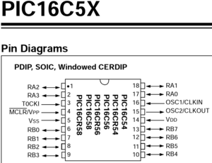
Datasheet is here https://www.microchip.com/en-us/product/PIC16C56 | |||
[[Image:pic16c56pinouts.png|thumb|left]] | |||
<br clear=all> | |||
=== MAX 232 === | |||
[[Image:max232.png|thumb|left]] | |||
<br clear=all> | |||
Latest revision as of 04:14, 2 January 2022
I have a Western Telematics, Inc RPB+ remote power strip. I picked it up on eBay.
It's a power strip with an RS232 port on it.
On the outside:
- 5 switched AC outlets, individually controllable
- Can switch up to 15A on one port, up to 15A for all ports.
- 9 pin RS232 port (use a null modem cable to connect)
- Dip switch for setting baud rate
- An LED for each outlet on the front panel to indicate power on state.
Inside it has:
- a PIC 16C56 microcontroller, in a socket
- 5 nice relays and associated drivers to interface to PIC
- a 555 timer
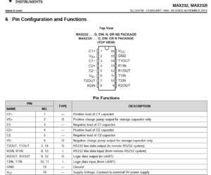
- an ADM232 on the serial port
- a power supply
A PIC 16C56 has:
- 18 pin DIP
- 1.5K memory
- 25 bytes of RAM (whew! takes my breath away!)
- 1 8-bit timer
- It's OTP = one time programmable
To substitute a flash device I could drop in a 16F628A, then I'd get 3.5k of RAM and 224 bytes of RAM. To do that though I'd need to understand what it's doing. Instead I plan on removing the ADM232, and adding an ESP32-Wrover-IE. I can drill a hole in the front panel to fit an external antenna; otherwise no signal will be going through the aluminum case. This will give me WiFi control of 5 devices.
Normal operation
Manual File:Wti power strip.pdf
There are DIP switches to set serial port rate. I keep it at 9600.
From bellman,
minicom --device /dev/ttyS0
The prompt is RPB+>
The menu should come up. If it does not try typing "/S", that gives you status.
- Dart
The basic command is "/n ON | OFF | BOOT", where "n" is a port number 1-5.
BOOT powers down, pauses, then powers up.
ESP32 operation
The ESP32 will need to have its UART connected to the UART of the RPB+. It will need to interface (I suppose) to Home Assistant on the WiFi side. I will make it look like one device with 5 power switches. I will ignore the "reboot" feature and just support "on" and "off".
It looks like ESPhome can handle all of this, of course. I am starting to think there is not anything I cannot do with ESPhome. There is a "UART Switch" component that does exactly what I need.
PIC 16C56
Datasheet is here https://www.microchip.com/en-us/product/PIC16C56

MAX 232
