Travel: Difference between revisions
Brian Wilson (talk | contribs) |
Brian Wilson (talk | contribs) |
||
| Line 88: | Line 88: | ||
==== GD32E103CA ==== | ==== GD32E103CA ==== | ||
Seed + Grove from Longan Labs https://github.com/Longan-Labs/Serial_CAN_FD_Module | Seed + Grove from Longan Labs https://github.com/Longan-Labs/Serial_CAN_FD_Module | ||
This board has a UART on its Grove port, so in theory Pi + Grove and I should be able to see it on a serial console. Right? Easy easy easy?? Then use AT commands to confirm it functions. | |||
=== ICSIM on Raspberry Pi === | === ICSIM on Raspberry Pi === | ||
| Line 100: | Line 102: | ||
===== Hardware ===== | ===== Hardware ===== | ||
[[File:Screenshot_from_2024-09-13_17-06-16.png|alt=|left|400x400px|SPI to Pi]] | |||
Xiao MCP2515 module: This article is a close match for what I am doing. [https://www.beyondlogic.org/adding-can-controller-area-network-to-the-raspberry-pi/ Adding CAN controller to Raspberry Pi] | Xiao MCP2515 module: This article is a close match for what I am doing. [https://www.beyondlogic.org/adding-can-controller-area-network-to-the-raspberry-pi/ Adding CAN controller to Raspberry Pi] '''I only bought one, grrr.''' | ||
It would be easier to connect the GD32 board since it's Grove, but I'd need | It would be easier to connect the GD32 board since it's Grove, but I'd need software for that. | ||
== Resources == | == Resources == | ||
Revision as of 00:54, 14 September 2024
TO DO
- Check tire pressure
- Remove luggage rack
- Mount bike rack
- Charge batteries for BT keyboard
- Charge battery in emergency phone
- Charge HT batteries
- Garmin 62 - load pocket queries
Hacking
- SenseCAP Indicator and cables
- Seeed CANBUS adapter
- Hookup Grove to CANBUS
- OBD-II to CANBUS
- Laptop and charger
- Laptop adapter (USB)
- Comp notebook
- USB3 hub
- 5V supply
- M5StickC with micropython and PIR hat
- M5 Atom Echo speaker
- 3 x USB-C cables
Raspberry Pi
- Pi 4
- 4" monitor
- Logitech KBD and mouse and USB dongle
- USB3 drive
Tools
- screwdrivers
- needle nose pliers
- small cutters
- red voltmeter
- usual tool kit in bag, screwdrivers, torx drivers, usb cables
CAN Bus
Open Garages
Connecting
I got an OBD-2 extension cable with 90 degree ends to make a low profile connection. I cut the cable in half. (Photo!) Now I have a connector with a 12" cable ready to use.
Termination
I don't need termination as long as my cable is less than 0.5m long. (It was 18" but I snipped it down to be on the safe side.)
Pinouts

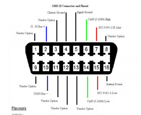
Signals that matter to me, and the wire colors:
5 signal ground -- orange
6 CANH -- Black
14 CANL -- Green
16 12V always on -- Brown
https://www.14core.com/wiring-the-mcp2515-shield-with-obd-on-arduino/ connector info
https://www.14core.com/wiring-the-mcp2515-controller-area-network-can-bus-diagnostics/
Interfaces
MCP2515
I intend trying the MCP2515 chip first because it's commonly used. Microchip MCP2515 datasheet
I got this breakout board: Seeed Xiao https://www.seeedstudio.com/Seeed-Studio-CAN-Bus-Breakout-Board-for-XIAO-and-QT-Py-p-5702.html
I got two, so one will have a 6 pin header soldered to the SPI connector and the other will have a Xiao ESP32C6 installed.
Seeed's board uses the TI SN65HVD23x 3.3-V CAN Bus Transceiver so it's all 3v3 and that means it can work with a Pi. Some older boards use 5V transceivers.
https://github.com/kvba1/ESP32-MCP2515-OBD2-CANBUS ESP32 + MC2515
https://github.com/yogiD/MCP2515-OBD Arduino + MCP2515
GD32E103CA
Seed + Grove from Longan Labs https://github.com/Longan-Labs/Serial_CAN_FD_Module
This board has a UART on its Grove port, so in theory Pi + Grove and I should be able to see it on a serial console. Right? Easy easy easy?? Then use AT commands to confirm it functions.
ICSIM on Raspberry Pi
ICSIM = Instrument Cluster Simulator = test CAN bus without breaking your car. Also, you can do bench testing!
https://github.com/zombieCraig/ICSim
Software
Starting from Bookworm on a Pi 5
sudo apt-get install libsdl2-dev libsdl2-image-dev can-utils
Hardware

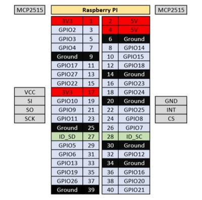
Xiao MCP2515 module: This article is a close match for what I am doing. Adding CAN controller to Raspberry Pi I only bought one, grrr.
It would be easier to connect the GD32 board since it's Grove, but I'd need software for that.
Resources
https://copperhilltech.com/ Pi and Arduino boards for CAN bus, OBD-2, NMEA, etc
Learn about CAN Bus from SEEED