CAN Bus: Difference between revisions
Brian Wilson (talk | contribs) |
Brian Wilson (talk | contribs) mNo edit summary |
||
| Line 50: | Line 50: | ||
Circuit Cellar article: '''eDash''' Robin Brophy Sep 2011 issue 254 | Circuit Cellar article: '''eDash''' Robin Brophy Sep 2011 issue 254 | ||
=== Connecting === | |||
I got an OBD-2 extension cable with 90 degree ends to make a low profile connection. I cut the cable in half. (Photo!) Now I have a connector with a 12" cable ready to use. | |||
==== Termination ==== | |||
https://electronics.stackexchange.com/questions/470382/can-bus-termination-resistors-for-can-logger-device | |||
I don't need termination as long as my cable is less than 0.5m long. (It was 18" but I snipped it down to be on the safe side.) | |||
==== Pinouts ==== | |||
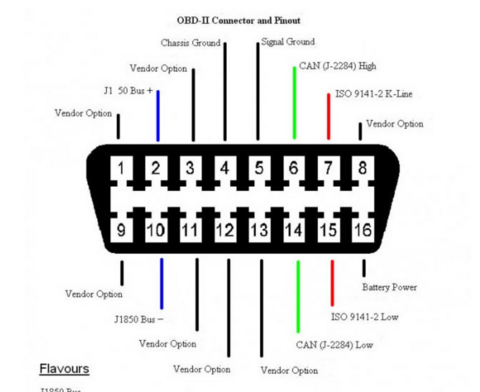
[[File:Screenshot 2024-09-13 124245.png|left|thumb|480x480px|OBD2 pinouts]] | |||
Signals that matter to me, and the wire colors: | |||
5 '''signal ground''' -- orange | |||
6 '''CANH''' -- Black | |||
14 '''CANL''' -- Green | |||
16 '''12V''' always on -- Brown | |||
https://www.14core.com/wiring-the-mcp2515-shield-with-obd-on-arduino/ connector info | |||
https://www.14core.com/wiring-the-mcp2515-controller-area-network-can-bus-diagnostics/ | |||
=== Interfaces === | |||
==== MCP2515 ==== | |||
I intend trying the MCP2515 chip first because it's commonly used. Microchip [https://ww1.microchip.com/downloads/en/DeviceDoc/MCP2515-Stand-Alone-CAN-Controller-with-SPI-20001801J.pdf MCP2515 datasheet] | |||
I got this breakout board: Seeed Xiao https://www.seeedstudio.com/Seeed-Studio-CAN-Bus-Breakout-Board-for-XIAO-and-QT-Py-p-5702.html | |||
I got two, so one will have a 6 pin header soldered to the SPI connector and the other will have a Xiao ESP32C6 installed. | |||
Seeed's board uses the TI [https://www.ti.com/lit/ds/symlink/sn65hvd230.pdf?ts=1685579002848&ref_url=https%253A%252F%252Fwww.google.com%252F SN65HVD23x 3.3-V CAN Bus Transceiver] so it's all 3v3 and that means it can work with a Pi. Some older boards use 5V transceivers. | |||
https://github.com/kvba1/ESP32-MCP2515-OBD2-CANBUS ESP32 + MC2515 | |||
https://github.com/yogiD/MCP2515-OBD Arduino + MCP2515 | |||
==== GD32E103CA ==== | |||
Seed + Grove from Longan Labs https://github.com/Longan-Labs/Serial_CAN_FD_Module | |||
This board has a UART on its Grove port, so in theory Pi + Grove and I should be able to see it on a serial console. Right? Easy easy easy?? Then use AT commands to confirm it functions. | |||
Since I have a RP2040 + Grove set up already I am going there first. [[Raspberry_Pi_RP2040]] | |||
=== ICSIM on Raspberry Pi === | |||
ICSIM = Instrument Cluster Simulator = test CAN bus without breaking your car. Also, you can do bench testing! | |||
https://github.com/zombieCraig/ICSim | |||
===== Software ===== | |||
Starting from Bookworm on a Pi 5 | |||
sudo apt-get install libsdl2-dev libsdl2-image-dev can-utils | |||
===== Hardware ===== | |||
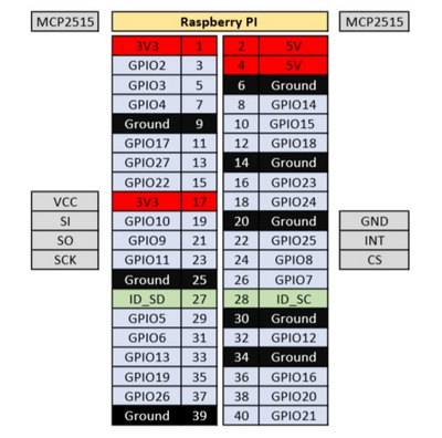
[[File:Screenshot_from_2024-09-13_17-06-16.png|alt=|left|400x400px|SPI to Pi]] | |||
Xiao MCP2515 module: This article is a close match for what I am doing. [https://www.beyondlogic.org/adding-can-controller-area-network-to-the-raspberry-pi/ Adding CAN controller to Raspberry Pi] '''I only bought one, grrr.''' | |||
It would be easier to connect the GD32 board since it's Grove, but I'd need software for that. | |||
== Resources == | == Resources == | ||
https://copperhilltech.com/ Pi and Arduino boards for CAN bus, OBD-2, NMEA, etc | |||
[https://www.seeedstudio.com/blog/2019/11/27/introduction-to-can-bus-and-how-to-use-it-with-arduino/ Learn about CAN Bus] from SEEED | |||
Call it car hacking or CAN hacking https://illmatics.com/carhacking.html | Call it car hacking or CAN hacking https://illmatics.com/carhacking.html | ||
https://medium.com/@yogeshojha/car-hacking-101-practical-guide-to-exploiting-can-bus-using-instrument-cluster-simulator-part-i-cd88d3eb4a53 | |||
[https://www.elmelectronics.com/help/obd/software/ Elm Electronics] the folks who make the interface. | [https://www.elmelectronics.com/help/obd/software/ Elm Electronics] the folks who make the interface. | ||
Revision as of 00:50, 26 September 2024
I got my ELM usb adapter from SECONS in Prague, around 100 years ago.
http://www.obd-2.com/ See also tenrec not 8track, which has been gone for a decade.
2022-12-10 back looking at this, at least a hundred years have elapsed (Linux time) since I started this page.
CAN interfaces
Raspberry Pi
2024-09-25 I unpacked these 2 Waveshare Pi hats today. They both have handy features like jumpers or dip switches to select termination and TVS protection.
Waveshare RS485 CAN HAT (Pi Zero footprint) Includes both MCP2515 and MAX485 transceivers; I don't have a use for RS485 at the moment.
Waveshare 2-channel CAN HAT (full size Pi footprint) Includes 2 MCP2515 transceivers, so you can do loop back testing, handy. Or put one on the instrumentation bus and one on the OBD II port?
Waveshare has a CAN FD board too, but I don't think I need that right now.
Open hardware Pi CAN Board Controller Area Network based on the MCP2515 controller.
WICAN from Meat Pi, based on the ESP32C3, here is their github page. https://github.com/meatpiHQ/wican-fw
Grove
See Grove.
SEEED Studio CAN-BUS module and the ODB II CAN BUS development kit, each about about $20
https://www.seeedstudio.com/blog/2019/11/27/introduction-to-can-bus-and-how-to-use-it-with-arduino/
There is a newer Seeed Studio "Serial CAN FD module", $4.90, I bought two, from Digikey. See https://docs.longan-labs.cc/114992978/ It has its own MCU, it's a GD32E103 which is based on the ARM Cortex M4. (Of course)
Other
https://www.hackster.io/kenliao/vehicle-gui-can-bus-display-05fb45
Sparkfun UBM32 controller: USB 32-Bit Whacker - PIC32MX795 Development Board $40
Software
https://github.com/nopnop2002/esp-idf-CANBus-Monitor There is an ESP32-C3 version too.
Dashboards
"RealDash" looks like it might be fun. It runs on Android, maybe I could use an old phone or tablet. I have enough of those now.
Circuit Cellar article: eDash Robin Brophy Sep 2011 issue 254
Connecting
I got an OBD-2 extension cable with 90 degree ends to make a low profile connection. I cut the cable in half. (Photo!) Now I have a connector with a 12" cable ready to use.
Termination
I don't need termination as long as my cable is less than 0.5m long. (It was 18" but I snipped it down to be on the safe side.)
Pinouts

Signals that matter to me, and the wire colors:
5 signal ground -- orange
6 CANH -- Black
14 CANL -- Green
16 12V always on -- Brown
https://www.14core.com/wiring-the-mcp2515-shield-with-obd-on-arduino/ connector info
https://www.14core.com/wiring-the-mcp2515-controller-area-network-can-bus-diagnostics/
Interfaces
MCP2515
I intend trying the MCP2515 chip first because it's commonly used. Microchip MCP2515 datasheet
I got this breakout board: Seeed Xiao https://www.seeedstudio.com/Seeed-Studio-CAN-Bus-Breakout-Board-for-XIAO-and-QT-Py-p-5702.html
I got two, so one will have a 6 pin header soldered to the SPI connector and the other will have a Xiao ESP32C6 installed.
Seeed's board uses the TI SN65HVD23x 3.3-V CAN Bus Transceiver so it's all 3v3 and that means it can work with a Pi. Some older boards use 5V transceivers.
https://github.com/kvba1/ESP32-MCP2515-OBD2-CANBUS ESP32 + MC2515
https://github.com/yogiD/MCP2515-OBD Arduino + MCP2515
GD32E103CA
Seed + Grove from Longan Labs https://github.com/Longan-Labs/Serial_CAN_FD_Module
This board has a UART on its Grove port, so in theory Pi + Grove and I should be able to see it on a serial console. Right? Easy easy easy?? Then use AT commands to confirm it functions.
Since I have a RP2040 + Grove set up already I am going there first. Raspberry_Pi_RP2040
ICSIM on Raspberry Pi
ICSIM = Instrument Cluster Simulator = test CAN bus without breaking your car. Also, you can do bench testing!
https://github.com/zombieCraig/ICSim
Software
Starting from Bookworm on a Pi 5
sudo apt-get install libsdl2-dev libsdl2-image-dev can-utils
Hardware

Xiao MCP2515 module: This article is a close match for what I am doing. Adding CAN controller to Raspberry Pi I only bought one, grrr.
It would be easier to connect the GD32 board since it's Grove, but I'd need software for that.
Resources
https://copperhilltech.com/ Pi and Arduino boards for CAN bus, OBD-2, NMEA, etc
Learn about CAN Bus from SEEED
Call it car hacking or CAN hacking https://illmatics.com/carhacking.html
Elm Electronics the folks who make the interface.
OBDtester and pyOBD
OBD Auto Doctor Free and paid versions, including Linux. The paid version is $20 per year.
Python
There are around 700 forks of pyobd... the one that shows up in pypi.org I think appears to be Brendan Whitfield's.
This one looks interesting too though. barracuda-fsh / pyobd